
Page 68 - 2017-Swift-Group-Motorhomes-Handbook-web
P. 68
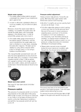
PRESSURE SWITCH

Waste water system                                Pressure switch adjustment                         SERVICES
1. The waste water holding tank is secured       Pressure Switch Adjustment, Truma/Flo-Jet
                                                  pump. (Normally Grey upper section with
   underneath the chassis of your motorhome       White lower section/valve housing)
   and is gravity fed.                            • A ll of the Truma/Flo-Jet pumps used by Swift

2. In order to eliminate unpleasant odours as      are pre-set at 25psi - 31psi.
   much as possible, only smooth bore pipes       • To further adjust the pressure switch setting,
   are used.
                                                    a cover cap must be first be removed from
However, should the waste water tank be            the end of the pump to reveal a pressure
overfilled, it is possible the waste water will     adjusting screw, as shown in the photos.
backfill the drain pipes until it eventually        A maximum of 1/4 turn clockwise or
appears in the shower base. In order to             anti-clockwise, from the factory setting, is
prevent this, please take note of part 3.           advised. Turning the screw clockwise 1/4
                                                    turn will increase the pressure switch cut-out
3. T he waste water gauge shows levels of          pressure, turning the screw anti-clockwise
   the tank in quarter increments, and it is        will reduce the pressure setting.
   recommended that the waste water tank          • P lease note a second screw mounted
   level is checked on a daily basis, emptying      below the cover cap is set in position with
   the tank when required. The tank can be          threadlock, this should not be disturbed.
   drained by using either a handle within
   a bed or storage space, or, by using a                                               Cover cap
   furniture mounted switch.

The manual/handle operated drain valve will
take the same appearance as that shown for
the fresh water tank, on page 51. If a furniture
mounted switch is fitted, it will be printed
with a graphics similar to the image 'waste
drain valve switch, below, and will usually be
positioned on the furniture above the entrance
door.

Waste tank drain switch                                         Pressure switch
                                                                adjusting screw
See page 51 fresh tank details for further
information                                       The pump may have to be removed to gain
                                                  access to the adjusting screw. Drain the water
Pressure switch                                   system before removing the pump.
                                                  To remove the pump pull the blue taps at right
The purpose of a pressure switch is to monitor    angles to the pipe work and lift the pump out.
the pressure on the outlet side of the pump.
When a tap is closed, and the pump continues
to run, there is an increase of pressure in the
system, and when that pressure reaches a
pre-set limit, the pressure switch will turn the
pump off.

                                                                                                     55