
Page 85 - 2017-Swift-Group-Motorhomes-Handbook-web
P. 85
SWIFT COMMAND POWER CONTROL SYSTEM
ELECTRICS
Fig 1
1. Introduction 2. Using the System
This section of the handbook will guide you 2.1 Power Supply Unit - Component
through the operation of the electrical system. Layout (see image above)
The PSU is located in the bed box or is
Further technical details are contained in mounted into furniture.
section 3 or in the supporting technical manual
available from www.sargentltd.co.uk 2.2 Activating the System
The EC600 system has a shutdown feature
For the safe operation of all electrical that can be used when the vehicle is in
equipment within your Leisure Vehicle it is storage. This allows the leisure electronics
important that you read and fully understand to be turned off when not required to save
these instructions. If you are unsure of any battery power. When in the off state the alarm
point please contact your dealer / distributor and tracking system supplies are still active, all
for advice before use. other supplies are turned off.
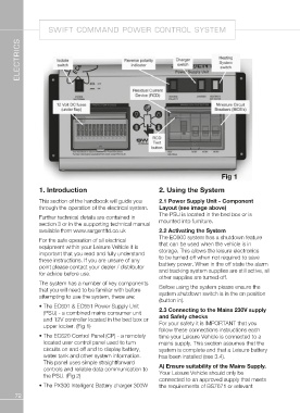
The system has a number of key components Before using the system please ensure the
that you will need to be familiar with before system shutdown switch is in the on position
attempting to use the system, these are: (button in).
• The EC601 & EC651 Power Supply Unit 2.3 Connecting to the Mains 230V supply
(PSU) - a combined mains consumer unit and Safety checks
and 12V controller located in the bed box or For your safety it is IMPORTANT that you
upper locker. (Fig 1) follow these connections instructions each
time your Leisure Vehicle is connected to a
• The EC620 Control Panel (CP) - a remotely mains supply. This section assumes that the
located user control panel used to turn system is complete and that a Leisure battery
circuits on and off and to display battery, has been installed (see 3.4).
water tank and other system information.
This panel uses simple straightforward A) Ensure suitability of the Mains Supply.
controls and reliable data communication to Your Leisure Vehicle should only be
the PSU. (Fig 2) connected to an approved supply that meets
the requirements of BS7671 or relevant
• T he PX300 Intelligent Battery charger 300W
72